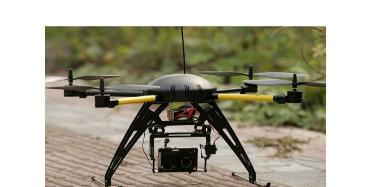
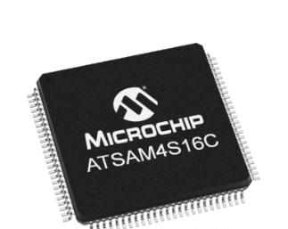
基于Atmel ATSAM4S16-AU主控芯片的的四轴飞行器解决方案
 333
333
 拍明
拍明
原标题:基于Atmel ATSAM4S16-AU主控芯片的的四轴飞行器解决方案
方案介绍
四轴飞行器是一种有四个螺旋桨且螺旋桨呈十字形布局的小型飞行器,属于多旋翼飞行器中最基本的一种。四轴飞行器具有可靠的稳定性,在复杂、危险的环境下可完成特定的飞行任务。它的应用十分广泛,可用于救援物资投放、航拍,桥梁检测,定点巡航等应用,具有不可估量的市场潜。
ATSAM4S16-AU 属于 Atmel 推出的 SAM4S 系列,Atmel® SAM4S 系列拓展了 Atmel ortex-M 产品组合,增强了性能,提高了电源效率,具有 2MB 闪存和 160KB SRAM 的较高存储密度,有用于连接、系统控制和模拟接口的丰富外设套件,它丰富的接口资源更适用于要将所有数据连入的飞控 MCU。
更重要的是,四轴飞行器有很多来自 IMU 的数据需要处理,而且还有复杂的控制算法,对于主控 MCU 的性能要求较高,ATSAM4S16-AU 为 Cortex-M4 内核,继承了 ARM 的优良性能,主频可达 120 MHz,可以完成四轴飞行器复杂的功能和精准的控制,且采用封装为 100-LQFP,较小的尺寸更加适用对于体积要求较高的飞行器。

【ATSAM4S16-AU】
描述ICMCU32BIT1MBFLASH100LQFP
制造商标准提前期12周
详细描述ARM®Cortex®-M4微控制器ICSAM4S32-位120MHz1MB(1Mx8)闪存100-LQFP(14x14)
类别集成电路(IC)
嵌入式-微控制器
制造商MicrochipTechnology
系列SAM4S
包装托盘
零件状态在售
核心处理器ARM®Cortex®-M4
核心尺寸32-位
速度120MHz
连接性EBI/EMI,I2C,IrDA,存储卡,SPI,SSC,UART/USART,USB
外设欠压检测/复位,DMA,POR,PWM,WDT
I/O数79
程序存储容量1MB(1Mx8)
程序存储器类型闪存
EEPROM容量-
RAM容量128Kx8
电压-电源(Vcc/Vdd)1.62V~3.6V
数据转换器A/D16x12b,D/A2x12b
振荡器类型内部
工作温度-40°C~85°C(TA)
封装/外壳100-LQFP
供应商器件封装100-LQFP(14x14)
基本零件编号ATSAM4S16
【ATSAM4S16C】

Features:
ARM Cortex-M4 running at up to 120 MHz
Memory Protection Unit (MPU)
DSP Instructions, Floating Point Unit (FPU), Thumb®-2 instruction set
1024 Kbytes Dual-Bank embedded Flash, ECC, Security Bit and Lock Bits
128 Kbytes embedded SRAM
16 Kbytes ROM with embedded boot loader routines (UART, USB) and IAP routines
Device Overview
Summary
For New Designs, we highly recommend to consider Revision B for Prototypes and Production.
Microchip's ARM®-based SAM 4S16 microcontroller builds on the high-performance 32-bit Cortex®-M4 core.
The SAM4S16 features:
Maximum operating speed of 120MHz
1MB of flash memory and 128KB of SRAM
1.62V to 3.6V supply
Power consumption 200uA/MHz in dynamic mode at low operating frequency, 30mA at 100MHz and 3uA at 1.8V in back-up mode with the RTC running
External bus interface supports SRAM, PSRAM, NOR Flash, LCD module and NAND Flash
Extensive peripheral set for connectivity, system control and analog interfacing
Native support for Microchip QTouch capacitive touch technology for implementation of buttons, sliders and wheels
Pin-to-pin compatible with Microchip SAM7S, SAM3N and SAM3S MCUs
Parallel Input/Output (IO) data capture mode
Get started with your application development now with the SAM4S evaluation kit, integrating a comprehensive development tool and software package. To reduce your time-to-market, Microchip and industry-leading third parties provide a worldwide support ecosystem.
Additional Features
Microcontroller Features
Core
ARM Cortex-M4 running at up to 120 MHz
Memory Protection Unit (MPU)
DSP Instructions, Floating Point Unit (FPU), Thumb®-2 instruction set
Memories
1024 Kbytes embedded Flash, ECC, Security Bit and Lock Bits
128 Kbytes embedded SRAM
16 Kbytes ROM with embedded boot loader routines (UART, USB) and IAP routines
8-bit Static Memory Controller (SMC): SRAM, PSRAM, NOR and NAND Flash support
External Bus Interface - 8-bit data, 4 chip selects, 24-bit address
System
Embedded voltage regulator for single-supply operation
Power-on-Reset (POR), Brown-out Detector (BOD) and Dual Watchdog for Safe Operation
Quartz or ceramic resonator oscillators: 3 to 20 MHz with clock failure detection and 32.768 kHz for RTT or system clock
RTC with Gregorian and Persian Calendar Mode, Waveform Generation in Backup mode
RTC counter calibration circuitry compensates for 32.768 kHz crystal frequency inaccuracy
Slow clock internal RC oscillator as permanent low-power mode device clock
High-precision 8/12 MHz factory-trimmed internal RC oscillator with 4 MHz default frequency for device startup, in-application trimming access for frequency adjustment
Two PLL up to 240 MHz for Device Clock and for USB
Temperature Sensor
Low-power tamper detection on two inputs, anti-tampering by immediate clear of general-purpose backup registers (GPBR)
22 Peripheral DMA Controllers
Low Power modes
Sleep, Wait and Backup modes; consumption down to 1 μA in Backup mode
Package
100-lead LQFP, 14 x 14 mm, pitch 0.5 mm
100-lead TFBGA, 9 x 9 mm, pitch 0.8 mm
100-lead VFBGA, 7 x 7 mm, pitch 0.65 mm
Temperature operating range
Revision A - Industrial (-40° C to +85° C), Revision B -(-40° C to +105° C)
Peripheral Features
USB 2.0 Device: 12 Mbps, 2668 byte FIFO, up to 8 bidirectional Endpoints, on-chip transceiver
Up to two USARTs with ISO7816, IrDA®, RS-485, SPI, Manchester and Modem Mode
Two 2-wire UARTs
Up to two 2-Wire Interface modules (I2C-compatible), one SPI, one Serial Synchronous Controller (I2S), one high-speed Multimedia Card Interface (SDIO/SD Card/MMC)
Two 3-channel 16-bit Timer Counters with capture, waveform, compare and PWM mode, Quadrature decoder logic and 2-bit Gray up/down counter for stepper motor
4-channel 16-bit PWM with complementary output, fault input, 12-bit dead time generator counter for motor control
32-bit Real-time Timer and RTC with calendar, alarm and 32 kHz trimming features
256-bit General Purpose Backup Registers (GPBR)
32-bit Cyclic Redundancy Check Calculation Unit (CRCCU) for data integrity check of off-/on-chip memories
I/O
79 I/O Lines with external interrupt capability (edge or level sensitivity), debouncing, glitch filtering and on-die series resistor termination
Three 32-bit Parallel Input/Output Controllers, Peripheral DMA-assisted Parallel Capture mode
Analog Features
16-channel, 1Msps ADC with differential input mode and programmable gain stage and auto calibration
One 2-channel 12-bit 1Msps DAC
One Analog Comparator with flexible input selection, selectable input hysteresis
Debugger Development Support
Serial Wire/JTAG Debug Port(SWJ-DP)
Debug access to all memories and registers in the system, including Cortex-M4 register bank when the core is running, halted, or held in reset.
Serial Wire Debug Port (SW-DP) and Serial Wire JTAG Debug Port (SWJ-DP) debug access.
Flash Patch and Breakpoint (FPB) unit for implementing breakpoints and code patches.
Data Watchpoint and Trace (DWT) unit for implementing watchpoints, data tracing, and system profiling.
Instrumentation Trace Macrocell (ITM) for support of printf style debugging.
IEEE1149.1 JTAG Boundary-scan on all digital pins.
Integrated Software Libraries and Tools
ASF-Atmel software Framework – SAM software development framework
Integrated in the Atmel Studio IDE with a graphical user interface or available as standalone for GCC, IAR compilers.
DMA support, Interrupt handlers Driver support
USB, TCP/IP, Wi-Fi and Bluetooth, Numerous USB classes, DHCP and Wi-Fi encryption Stacks
RTOS integration, FreeRTOS is a core component
Parametrics
Name
Value
Part Family
ATSAM4S16C
Max CPU Speed MHz
120
Program Memory Size (KB)
1024
SRAM (KB)
128
Auxiliary Flash (KB)
0.512
SDIO/SD-CARD/eMMC
1
Temperature Range (C)
-40 to 85
Operating Voltage Range (V)
1.62 to 3.6
Direct Memory Access Channels
22
SPI
3
I2C
2
Peripheral Pin Select / Pin Muxing
Yes
Number of USB Modules
1
ADC Input
15
Max ADC Resolution (Bits)
12
Max ADC Sampling Rate (ksps)
1000
Number of DACs
1
Input Capture
12
Max 16-bit Digital Timers
6
Parallel Port
EBI
Number of Comparators
1
Internal Oscillator
4,8,12Mhz,32Khz
Hardware RTCC/RTC
Yes
Max I/O Pins
79
Pincount
100
Quadrature Encoder Interface
2
责任编辑:David
【免责声明】
1、本文内容、数据、图表等来源于网络引用或其他公开资料,版权归属原作者、原发表出处。若版权所有方对本文的引用持有异议,请联系拍明芯城(marketing@iczoom.com),本方将及时处理。
2、本文的引用仅供读者交流学习使用,不涉及商业目的。
3、本文内容仅代表作者观点,拍明芯城不对内容的准确性、可靠性或完整性提供明示或暗示的保证。读者阅读本文后做出的决定或行为,是基于自主意愿和独立判断做出的,请读者明确相关结果。
4、如需转载本方拥有版权的文章,请联系拍明芯城(marketing@iczoom.com)注明“转载原因”。未经允许私自转载拍明芯城将保留追究其法律责任的权利。
拍明芯城拥有对此声明的最终解释权。


 产品分类
产品分类


 2012- 2022 拍明芯城ICZOOM.com 版权所有 客服热线:400-693-8369 (9:00-18:00)


