Microchip ATA6570高速案CAN收发器解决方案
 212
212
 拍明
拍明
原标题:Microchip ATA6570高速案CAN收发器解决方案
microchip公司的ATA6570是单独可用具有局部网络的高速控制器区域网络(CAN)收发器,完全和ISO 11898-2, ISO11898-5, ISO11898-6, ISO/DIS 11898-2 (2016)以及SAEJ2962-2兼容,标准CAN数据速率高达1Mbps,CAN FD数据速率高达5Mbps(CAN FD),4Mbps SPI接口,能直接和3.3V-5V MCU接口,主要用在汽车环境.本文介绍了ATA6570主要特性,框图,以及ATAB657XA开发板主要特性,电路图,材料清单和PCB设计图.
The Atmel® ATA6570 is a standalone high speed CAN transceiver that interfaces a Controller Area Network (CAN) protocol controller and the physical two wire CAN bus designed for high speed CAN applications in the automotive environment.
It provides local and enhanced remote wake-up capabilities and is available in a SO14 package. The Atmel ATA6570 has a very low power consumption in Standby and Sleep Mode. Beside local wake-up via WAKE and remote wake-up pattern according to ISO 11898-5, ATA6570 additionally supports ISO11898-6 compliant CAN partial networking. A CAN frame decoder evaluates the bus traffic and checks for a matching frame, that has being configured into registers via the SPI. The device is able to keep the complete ECU in a low power mode even when bus traffic is present until a valid wake-up frame is received. It also features a watchdog and a Serial Peripheral Interface (SPI).
The Atmel ATA6570 is a CAN-FD device and can be easily configured via the SPI as Non-FD (meaning only for Classical CAN), CAN FD silent, CAN FD passive or as CAN FD active device, in order to fulfill the corresponding application requirements.
The VIO pin allows the automatic adjustment of the I/O levels to the I/O level of the connected microcontroller.The SPI interface controls the device and provides status and diagnosis information to the Host MCU.All these features make the Atmel ATA6570 an excellent choice for high speed CAN networks, especially in applications where nodes are always connected with the battery but are only activated when they are really needed in the application.
ATA6570主要特性:
• High speed CAN transceiver fully compliant to ISO 11898-2, ISO11898-5, ISO11898-6, ISO/DIS 11898-2 (2016) and SAEJ2962-2
• Autonomous bus biasing according to ISO 11898-6
• Low electromagnetic emission (EME) and high electromagnetic immunity (EMI)
• Standard CAN data rate up to 1Mbit/s and CAN FD data rate up to 5Mbit/s (CAN FD)
• 4Mbit/s SPI interface
• Differential bus receiver with wide common mode range
• Very low current consumption in Sleep and Standby with fully wake-up capability
• Power-down of the complete node via the INH-output (switching off external voltage regulator(s))
• Six operation modes
– Power off mode
– Microcontroller Reset mode
– Sleep mode
– Standby mode
– Normal mode
– Overtemp mode
• Four wake-up sources
– Local wake-up via pin WAKE
– Remote wake-up pattern according to ISO 11898-5
– Remote wake-up frame according to ISO 11898-6 (selective wake-up)
– Host wake-up via SPI
• Wake-up source recognition
• Transceiver disengages from the bus in over-temperature and low power supply mode
• RXD recessive clamping detection
• Transmit data (TXD) dominant timeout function
• Undervoltage detection on VS, VCC and VIO pins
• Overtemperature protection
• 3.3V to 5V microcontrollers can be interfaced directly via the VIO pin
• Battery supply and CAN bus pins protected against transients according to ISO7637
• High Electro Static Discharge (ESD) Handling Capability on the Bus Pins
• Bus pins short-circuit protected to GND and VCC
• VS operating voltage up to 28V, VS DC supply voltage up to 42V
• Watchdog with independent clock source
• Watchdog can be operated in Window and Timeout mode
– Optional cyclic wake-up in watchdog Timeout mode
– Watchdog automatically re-enabled when wake-up event captured
– Watchdog period selectable
– Watchdog reset period selectable
• Qualified according to AEC-Q100
• Fulfills the OEM Hardware Requirements for CAN Interfaces in Automotive Applications, Rev. 1.3
• Fulfills the OEM Requirements for Partial Networking Rev. 2.2
• SO14 Package

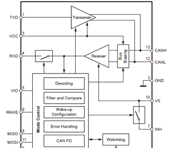
图1. ATA6570简化框图
开发板ATAB657XA
The development board ATAB657XA is a hardware platform to evaluate the new ATA657X CAN device family and it enables users to rapidly prototype and test new CAN designs with the ATA657X ICs.

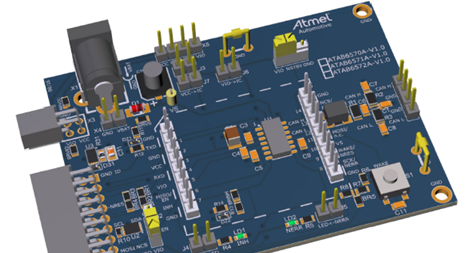
图2. 开发板ATAB657XA外形图
ATAB657XA开发板主要特性:
• All components necessary to put the ATA6570, ATA6571 or ATA6572 into operation are included
• Placeholders for some optional components for extended functions
• All pins are easily accessible
• Switching into Normal, Standby or Sleep mode via two jumpers (ATA6571)
• Push button included for creating a local wake-up after entering Sleep mode
• LEDs for operation indication
• Ground coulter clip for easy probe connection while measuring with oscilloscope
• Connectors for direct plug-in with the C21-XPRO Xplained board (only ATA6570 and ATA6572 with SPI)
ATAB657XA开发板包括:
• ATAB657XA Development Board (ADM00870)
• Important Information Sheet

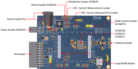
图3. ATAB657XA开发板概述图
ATAB6570开发板材料清单:


ATAB6571开发板材料清单


ATAB6572开发板材料清单


详情请见:
责任编辑:HanFeng
【免责声明】
1、本文内容、数据、图表等来源于网络引用或其他公开资料,版权归属原作者、原发表出处。若版权所有方对本文的引用持有异议,请联系拍明芯城(marketing@iczoom.com),本方将及时处理。
2、本文的引用仅供读者交流学习使用,不涉及商业目的。
3、本文内容仅代表作者观点,拍明芯城不对内容的准确性、可靠性或完整性提供明示或暗示的保证。读者阅读本文后做出的决定或行为,是基于自主意愿和独立判断做出的,请读者明确相关结果。
4、如需转载本方拥有版权的文章,请联系拍明芯城(marketing@iczoom.com)注明“转载原因”。未经允许私自转载拍明芯城将保留追究其法律责任的权利。
拍明芯城拥有对此声明的最终解释权。


 产品分类
产品分类


 2012- 2022 拍明芯城ICZOOM.com 版权所有 客服热线:400-693-8369 (9:00-18:00)


