


 产品分类
产品分类
基于TI公司TIDA-01179 30W汽车前端电源参考设计
 295
295
 拍明
拍明
原标题:TI TIDA-01179 30W汽车前端电源参考设计
TI公司的TIDA-01179是30W汽车前端电源参考设计,包括了两个DC/DC转换器:第一个为降压-升压DC/DC转换器,满足ISO 7637-2和ISO16750-2标准;第二个是低成本紧凑的降压转换器,输出高达20W.系统还包括反向电池保护,电瞬变保护和EMI滤波器.参考设计能处理所有的电池所有情况,输入电压3- 36V DC,主要用在HEV/EV牵引逆变器,电子控制单元,电池前端电源和干式双离合器变速器.本文介绍了参考设计TIDA-01179主要特性,框图,HEV/EV牵引逆变器系统框图以及参考设计TIDA-01179电路图,材料清单和PCB设计图.
描述
TIDA-01179 参考设计是汽车前端电源,可为 12V 的车载电池提供 30W 的最大输出。第一级是降压-升压直流/直流转换器,在 ISO 7637-2 和 ISO 16750-2 标准中规定的 12V 电池条件的完整直流范围内维持稳定的 15V 输出电压。第二级是最多可支持 20W 输出的紧凑型降压转换器。
特性
宽输入电压降压-升压转换器,在直流 3V 到 36V(瞬态 42V)输入电压范围内具有极低的下降期间
专为 ISO 7637-2:2004 脉冲 1、2a 和 3a/b 严重情况(IV 级)而设计并通过测试
专为严苛的电池冷启动运行情况(ISO16750-2 III 级)而设计并通过测试
通过 CISPR25 传导 EMI(5 类)测试
此电路设计已经过测试、可装运且仅包含硬件
This reference design is an automotive front-endpower supply that able to supply a 30-W maximumoutput for the 12-V car battery. The first stage is abuck-boost DC/DC converter, which maintains a stableoutput voltage over the full DC range of the 12-Vbattery conditions specified in ISO 7637-2 and ISO16750-2 standards. Then a low-cost, compact buckconverter is connected to the buck-boost converterand enables up to a 20-W output. The system consistsof reverse battery protection, electrical transientprotections, and EMI filters. The EMI filter consists ofDM and CM respectively and is designed forcomplying conducted EMI standards per CISPR25.
This reference design is a wide input 30-W front-end power supply for a 12-V car battery in the HEV/EVtraction inverter system. It consists of two DC/DC converters. The first converter is a buckboostconverter, which handles a wide input range from the car battery and provides 15 V of constantoutput voltage at a 2-A output current. This 15-V rail can be used to power the system basis chip (SBC),the resolver, and the primary of the IGBT bias supply. Then a buck converter connected to the output ofbuck-boost converts the 15 V down to 5 V at 4.5 A. This 5 V can power the microcontrollers, ADconverters, safety diagnostic circuits, the primary sides of the current sensing, voltage sensing, and so on.
The TIDA-01179 is able to handle all battery conditions, which includes:
• The system maintains a constant output voltage over the full DC range of battery conditions specifiedin ISO 16750-2:
– Input VIN(min) down to 3.0 V simulating a severe cold cranking condition
– Input VIN(max) up to 28 V simulating the upper range of normal battery operation
• The system must clamp and filter high-voltage electrical fast transients and maintain operation throughthem:
– These pulses include clamped load dump (up to 38 V) and other transients outlined in ISO 7637-2:2004.
• The system must properly respond to a reverse battery polarity event and shut down appropriately.
• Filter design targets at the CISPR 25 automotive EMI standard for conducted emission suppression.
• The layout of the board must be done in such a way to minimize the footprint of the solution whilemaintaining high performance.
参考设计TIDA-01179主要特性:
• Wide-VIN Buck-Boost Converter During Very LowDips in Input Voltage of 3- to 36-V DC, 42-VTransient
• Low-Cost Buck Operates After the Buck-Boost With5-V and 4.5-A maximum output
• Reverse Battery Protection With Fast Shutdown
• Designed and Tested for Severe Battery ColdCrank Operations (ISO 16750-2 Level III)
• Designed and Tested for ISO 7637-2:2004 Pulse 1,2a, and 3a/b Severe Conditions (Level IV)
• Tested for CISPR25 Conducted EMI (Class 5)
参考设计TIDA-01179应用:
• HEV/EV Traction Inverter
• Dry Double Clutch Transmission
• Electronic Control Units
• Battery Front-End Power
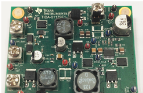
图1.参考设计TIDA-01179外形图
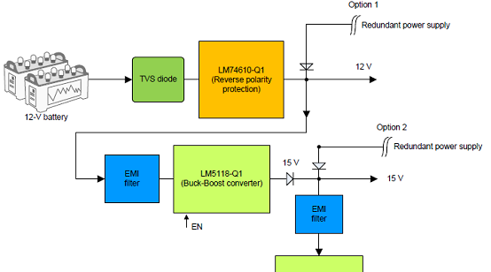
图2.参考设计TIDA-01179框图

图3.HEV/EV牵引逆变器系统框图和TIDA-01179的位置
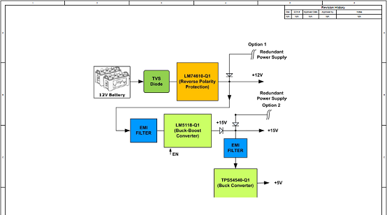
图4.参考设计TIDA-01179电路图(1)
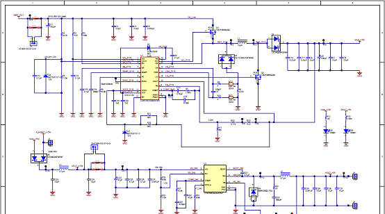
图5.参考设计TIDA-01179电路图(2)
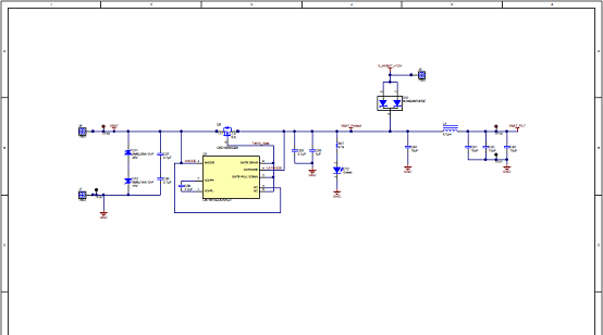
图6.参考设计TIDA-01179电路图(3)
参考设计TIDA-01179材料清单:
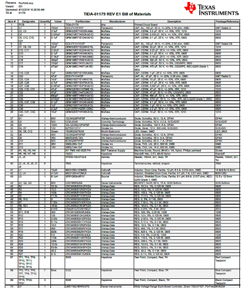
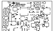
图7.参考设计TIDA-01179 PCB设计图(1)
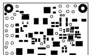
图8.参考设计TIDA-01179 PCB设计图(2)
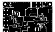
图9.参考设计TIDA-01179 PCB设计图(3)
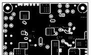
图10.参考设计TIDA-01179 PCB设计图(4)
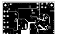
图11.参考设计TIDA-01179 PCB设计图(5)
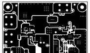
图12.参考设计TIDA-01179 PCB设计图(6)

图13.参考设计TIDA-01179 PCB设计图(7)

图14.参考设计TIDA-01179 PCB设计图(8)

图15.参考设计TIDA-01179 PCB设计图(9)
图16.参考设计TIDA-01179 PCB设计图(10)
详情请见:
责任编辑:Davia
【免责声明】
1、本文内容、数据、图表等来源于网络引用或其他公开资料,版权归属原作者、原发表出处。若版权所有方对本文的引用持有异议,请联系拍明芯城(marketing@iczoom.com),本方将及时处理。
2、本文的引用仅供读者交流学习使用,不涉及商业目的。
3、本文内容仅代表作者观点,拍明芯城不对内容的准确性、可靠性或完整性提供明示或暗示的保证。读者阅读本文后做出的决定或行为,是基于自主意愿和独立判断做出的,请读者明确相关结果。
4、如需转载本方拥有版权的文章,请联系拍明芯城(marketing@iczoom.com)注明“转载原因”。未经允许私自转载拍明芯城将保留追究其法律责任的权利。
拍明芯城拥有对此声明的最终解释权。
相关资讯
:
基于MC33771主控芯片的新能源锂电池管理系统解决方案

AMIC110 32位Sitara ARM MCU开发方案

基于AMIC110多协议可编程工业通信处理器的32位Sitara ARM MCU开发方案

基于展讯SC9820超低成本LTE芯片平台的儿童智能手表解决方案

基于TI公司的AM437x双照相机参考设计

基于MTK6580芯片的W2智能手表解决方案


 2012- 2022 拍明芯城ICZOOM.com 版权所有 客服热线:400-693-8369 (9:00-18:00)


