基于R7S910035/RBN40H125S1FPQ-A0主控器件的20kW高频UPS解决方案
 317
317
 拍明
拍明
方案概述
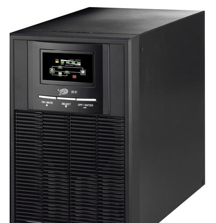
20kW的高频UPS设计是不带隔离变压器的产品,高频UPS在行业内多采用Digital Signal Processor(数字信号处理器)控制技术,实现高开关速率的IGBT和高速处理技术,实现高功率密度集成和小型化,提升产品性能和可靠性。
20kW高频UPS有成本上和体积上的压力。因此,RENESAS的G8H技术的IGBT最高可以做到1250V/75A,依旧采用的是TO-247的封装,电流规格相当于2个40A的管子且并联一致性更高。因封装体积小、电流规格大、并联一致性高, RENESAS的IGBT单管更适合设计成本低、功率密度高和体积小的20kW的高频UPS产品。
优势
• RENESAS公司的32位带浮点运算单元的RZ/T1系列MCU,型号是 R7S910035。该MCU集成逆变控制IP和安全加密功能,高采样的速度和精度,控制逆变输出的交流电与旁路的交流电保持同相,降低谐波并保证UPS与负载安全
【R7S910035】
RZ/T1 Group
300 MHz/450 MHz/600 MHz, MCU with ARM Cortex®-R4 and -M3*1, on-chip FPU, 498/747/996 DMIPS, up to 1 Mbyte of on-chip extended SRAM, Ethernet MAC, EtherCAT*1, USB 2.0 high-speed, CAN, various communications interfaces such as an SPI multi-I/O bus controller, ΔΣ interface, safety

Features
■ On-chip 32-bit ARM Cortex-R4 processor
• High-speed realtime control with maximum operating frequency of 300/450/600 MHz
Capable of 498/747/996 DMIPS (in operation at 300/450/600MHz)
• On-chip 32-bit ARM Cortex-R4 (revision r1p4)
• Tightly coupled memory (TCM) with ECC: 512 Kbytes/32 Kbytes
• Instruction cache/data cache with ECC: 8 Kbytes per cache • High-speed interrupt
• The FPU supports addition, subtraction, multiplication, division, multiply-and-accumulate, and square-root operations at singleprecision and double-precision.
• Harvard architecture with 8-stage pipeline
• Supports the memory protection unit (MPU)
• ARM CoreSight architecture, includes support for debugging through JTAG and SWD interfaces
■ On-chip 32-bit ARM Cortex-M3 processor (in products incorporating an R-IN engine)
• 150-MHz operating frequency • On-chip 32-bit ARM Cortex-M3 (revision r2p1) • RISC Harvard architecture with 3-stage pipeline • Supports the memory protection unit (MPU)
■ Low power consumption
• Standby mode, sleep mode, and module stop function
■ On-chip extended SRAM
• Up to 1 Mbyte of the on-chip extended SRAM with ECC
• 150 MHz
■ Data transfer
• DMAC: 16 channels × 2 units
• DMAC for the Ethernet controller: 1 channel
■ Event link controller
• Module operations can be started by event signals rather than by interrupt handlers.
• Linked operation of modules is available even while the CPU is in the sleep state.
■ Reset and power supply voltage control
• Four reset sources including a pin reset
• Dual power-voltage configuration: 3.3 V (I/O unit), 1.2 V (internal)
■ Clock functions
• External clock/oscillator input frequency: 25 MHz
• CPU clock frequency: Up to 300/450/600 MHz
• Low-speed on-chip oscillator (LOCO): 240 kHz
■ Independent watchdog timer
• Operated by a clock signal obtained by frequency-dividing the
clock signal from the low-speed on-chip oscillator: Up to 120 kHz
■ Safety functions
• Register write protection, input clock oscillation stop detection, CRC, IWDTa, and A/D self-diagnosis
• An error control module is incorporated to generate a pin signal output, interrupt, or internal reset in response to errors originating in the various modules.
■ Security functions (optional)*2
• Boot mode with security through encryption
■ Encoder interfaces (optional)*3
• EnDat 2.2, BiSS-C, FA-CODER, A-format, and HIPERFACE DSL-compliant interfaces*4
• Frequency-divided output from an encoder
■ Various communications interfaces • Ethernet
- EtherCAT slave controller: 2 ports (optional) - Ethernet MAC: 1 port (an Ethernet switch is not used)
or
- Ethernet MAC: 1 port (an Ethernet switch to support 2 ports is used) • USB 2.0 high-speed host/function : 1 channel • CAN (compliant with ISO11898-1): 2 channels (max.) • SCIFA with 16-byte transmission and reception FIFOs: 5 channels
• I2C bus interface: 2 channels for transfer at up to 400 kbps
• RSPIa: 4 channels
• SPIBSC: Provides a single interface for multi-I/O compatible serial flash memory
■ External address space
• Buses for high-speed data transfer at 75 MHz (max.) • Support for up to 6 CS areas • 8-, 16-, or 32-bit bus space is selectable per area
■ Up to 33 extended-function timers
• 16-bit TPUa (12 channels), MTU3a (9 channels), GPTa (4 channels): Input capture, output compare, PWM waveform output
• 16-bit CMT (6 channels), 32-bit CMTW (2 channels)
■ Serial sound interface (1 channel)
■ ΔΣ interface
• Up to 4 ΔΣ modulators are connectable externally.
■ 12-bit A/D converters
• 12 bits × 2 units (max.)
(8 channels for unit 0; 16 channels for unit 1)
• Self diagnosis
• Detection of analog input disconnection
■ Temperature sensor for measuring temperature within the chip
■ General-purpose I/O ports
• 5-V tolerance, open drain, input pull-up
■ Multi-function pin controller
• The locations of input/output functions for peripheral modules are selectable from among multiple pins.
■ Operating temperature range
• Tj = -40°C to +125°C
Tj: Junction temperaturefunctions, encoder interfaces*1, and security
functions*1
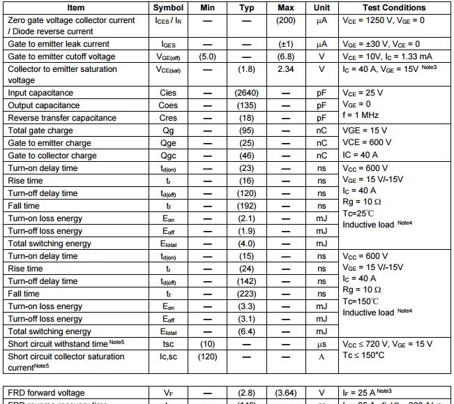
• RENESAS公司G8H技术的IGBT,型号主要是RBN40H125S1FPQ-A0(1250V/40A, Cres为18PF)和RBN75H125S1FP4-A0(1250V/75A,Cres为30PF)。该类型的IGBT减小C极与G极间的反向传输电容Cres,降低振铃,提高并联一致性,增加了产品的稳定性和降低产品应用过程中的故障率。
【RBN40H125S1FPQ-A0】
1250V - 40A - IGBT Application: Uninterruptible Power Supply
Features
Low collector to emitter saturation voltage
VCE(sat) = 1.8 V typ. (at IC = 40 A, VGE = 15 V, Ta = 25°C)
Built in fast recovery diode in one package
Trench gate and thin wafer technology (G8H series)
High speed switching
Short circuit withstands time (10 s min.)
Outline

Absolute Maximum Ratings

Note: Continuous heavy condition (e.g. high temperature/voltage/current or high variation of temperature) may affecta reliability even if it are within the absolute maximum ratings. Please consider derating condition for appropriatereliability in reference Renesas Semiconductor Reliability Handbook (Recommendation for Handling and Usage of Semiconductor Devices) and individual reliability data.

Notes:
1. PW 10 s, duty cycle 1%
2. Please use this device in the thermal conditions which the junction temperature does not exceed 175°C.Renesas IGBT Application Note is disclosed about reliability test and application condition up to 175°C.
3. Pulse test
4. Switching time test circuit and waveform are shown below.
5. Verified by design.
【UPS】
UPS(Uninterruptible Power System/Uninterruptible Power Supply),即不间断电源,是将蓄电池(多为铅酸免维护蓄电池)与主机相连接,通过主机逆变器等模块电路将直流电转换成市电的系统设备。主要用于给单台计算机、计算机网络系统或其它电力电子设备如电磁阀、压力变送器等提供稳定、不间断的电力供应。当市电输入正常时,UPS 将市电稳压后供应给负载使用,此时的UPS就是一台交流式电稳压器,同时它还向机内电池充电;当市电中断(事故停电)时, UPS 立即将电池的直流电能,通过逆变器切换转换的方法向负载继续供应220V交流电,使负载维持正常工作并保护负载软、硬件不受损坏。UPS 设备通常对电压过高或电压过低都能提供保护。

UPS是针对中国电网环境和网络监控及网络系统、医疗系统等对电源的可靠性要求,克服中、大型计算机网络系统集中供电所造成的供电电网环境日益恶劣的问题,以全新的数字技术研制出的第三代工频纯在线式智能型UPS。直流电源,是维持电路中形成稳恒电流的装置。如干电池、蓄电池、直流发电机等。
UPS和直流电源是企业重要的供电保障设备,传统的维护管理包括:①日常巡检外观,定期更换电池、滤波电容、风机等易损件,大修时做电池活化等;②改造或采用换代设备,使用高级工具测试电池性能。这种管理方式企业投入成本高,维护人员工作量大,不易实时掌握设备运行状态和关键数据,设备事故预防能力低。实施在线维护管理可避免传统方式的不足之处,获得良好效益。
UPS的中文意思为“不间断电源”,是英语“Uninterruptible Power System/Uninterruptible Power Supply”的缩写,它可以保障计算机系统在停电之后继续工作一段时间以使用户能够紧急存盘,使用户不致因停电而影响工作或丢失数据。
责任编辑:Davia
【免责声明】
1、本文内容、数据、图表等来源于网络引用或其他公开资料,版权归属原作者、原发表出处。若版权所有方对本文的引用持有异议,请联系拍明芯城(marketing@iczoom.com),本方将及时处理。
2、本文的引用仅供读者交流学习使用,不涉及商业目的。
3、本文内容仅代表作者观点,拍明芯城不对内容的准确性、可靠性或完整性提供明示或暗示的保证。读者阅读本文后做出的决定或行为,是基于自主意愿和独立判断做出的,请读者明确相关结果。
4、如需转载本方拥有版权的文章,请联系拍明芯城(marketing@iczoom.com)注明“转载原因”。未经允许私自转载拍明芯城将保留追究其法律责任的权利。
拍明芯城拥有对此声明的最终解释权。


 产品分类
产品分类


 2012- 2022 拍明芯城ICZOOM.com 版权所有 客服热线:400-693-8369 (9:00-18:00)


