


 产品分类
产品分类
基于Renesas公司的RX64M 32位MCU开发方案
 84
84
 拍明
拍明
原标题:Renesas RX64M 32位MCU开发方案
Renesas公司的RX64M是工作频率高达120MHz的32位RX mcu,采用功能强大的RXv2核,具有片上FPU,240DMIPS,多达4MB闪存,51KB SRAM,包括IEEE 1588兼容的以太网MAC,全速USB 2.0,SD主接口,四个SPI,CAN,12位ADC,RTC,加密,用于音频的串行接口和CMOS照相机接口在内的各种通信接口.工作电压2.7到3.6V,主要用在工业设备,网络设备和需要实时性能和大容量存储器的其它应用.本文介绍了RX64M主要特性,功能框图, RX64M RX64M入门套件主要特性, HMI扩展板框图,RX64M CPU板和HMI扩展板系统配置图以及HMI扩展板R0K50564MB001BR电路图和RX64M CPU板电路图.
The RX64M Group 32-bit microcontrollers are capable of operating at up to 120 MHz. The RX64M employs the powerfully evolved RXv2 core, which is backward compatible with the RX core employed in existing RX products. The RXv2 core enables 1.35 times the Coremark/MHz performance and a 40% reduction in power consumption compared to existing RX products, and even higher code efficiency, allowing the realization of high-speed, low consumption systems.
The RX64M Group is equipped with large-capacity memory of up to 4 MB of ROM for code and 552 KB work RAM. Built-in functions include the well-received event link controller from the RX200 and abundant functions from the RX63N, as well as SD card and audio interfaces, which are highly demanded by the market, and IEEE 1588 industrial Ethernet functions have been added. Thus, the RX64M Group is suitable for industrial equipment, network devices, and other applications requiring advanced real-time performance and large-capacity memory. We are also preparing a variety of middleware to support short system development times at low cost.
RX64M主要特性:
■ 32-bit RXv2 CPU core
Max. operating frequency: 120 MHz Capable of 240 DMIPS in operation at 120 MHz
Single precision 32-bit IEEE-754 floating point
Two types of multiply-and-accumulation unit (between memories and between registers)
32-bit multiplier (fastest instruction execution takes one CPU clock cycle)
Divider (fastest instruction execution takes two CPU clock cycles)
Fast interrupt
CISC Harvard architecture with 5-stage pipeline
Variable-length instructions: Ultra-compact code
Supports the memory protection unit (MPU)
JTAG and FINE (two-line) debugging interfaces
■ Low-power design and architecture
Operation from a single 2.7- to 3.6-V supply
Low power consumption: A product that supports all peripheral functions draws only 0.3mA/MHz (Typ.).
RTC is capable of operation from a dedicated power supply.
Four low-power modes
■ On-chip code flash memory, no wait states
Supports versions with up to 4 Mbytes of ROM
120-MHz operation, 8.3-ns read cycle (no wait states)
User code is programmable by on-board or off-board programming.
Programming/erasing as background operations (BGOs)
■ On-chip data flash memory
64 Kbytes, reprogrammable up to 100,000 times
Programming/erasing as background operations (BGOs)
■ On-chip SRAM
512 Kbytes of SRAM (no wait states)
32 Kbytes of RAM with ECC (one wait state, single-error correction and double error detection)
8 Kbytes of standby RAM (backup on deep software standby)
■ Data transfer
DMAC: 8 channels
DTC
EXDMAC: 2 channels
DMAC for the Ethernet controller: 3 channels for 176- and 177-pin products; 2 channels for 100-, 144-, and 145-pin products
■ Reset and supply management
Power-on reset (POR)
Low voltage detection (LVD) with voltage settings
■ Clock functions
External crystal oscillator or internal PLL for operation at 8 to 24 MHz
Internal 240-kHz LOCO and HOCO selectable from 16, 18, and 20 MHz
120-kHz clock for the IWDTa
■ Real-time clock
Adjustment functions (30 seconds, leap year, and error)
Real-time clock counting and binary counting modes are selectable
Time capture function (for capturing times in response to event-signal input)
■ Independent watchdog timer
120-kHz (1/2 LOCO frequency) clock operation
■ Useful functions for IEC60730 compliance
Oscillation-stoppage detection, frequency measurement, CRC, IWDTa, self-diagnostic function for the A/D converter, etc.
Register write protection function can protect values in important registers against overwriting.
■ Various communications interfaces
IEEE 1588-compliant Ethernet MAC (for 176- and 177-pin products: 2 modules)
PHY layer for host/function or OTG controller (1) with full-speed USB 2.0 with battery charging transfer (only for 176- and 177-pin products)
PHY layer (1) for host/function or OTG controller (1) with fullspeed USB 2.0 transfer
CAN (compliant with ISO11898-1), incorporating 32 mailboxes (up to 3 modules)
SCIg and SCIh with multiple functionalities (up to 9) Choose from among asynchronous mode, clock-synchronous mode, smart-card interface mode, simplified SPI, simplified I2C, and extended serial mode.
SCIFA with 16-byte transmission and reception FIFOs (up to 4 interfaces)
I2C bus interface for transfer at up to 1 Mbps (up to 2 interfaces)
Four-wire QSPI (1 interface) in addition to RSPIa (1 interface)
Parallel data capture unit (PDC) for the CMOS camera interface (not in 100-pin products)
SD host interface (optional: 1 interface) with a 1- or 4-bit SD bus for use with SD memory or SDIO
■ External address space
Buses for full-speed data transfer (max. operating frequency of 60 MHz)
8 CS areas
8-, 16-, or 32-bit bus space is selectable per area
Independent SDRAM area (128 Mbytes)
■ Up to 29 extended-function timers
16-bit TPUa, MTU3a, and GPTa: input capture, output compare, PWM waveform output
8-bit TMRa (4 channels), 16-bit CMT (4 channels), 32-bit CMTW (2 channels)
■ 12-bit A/D converter
Two 12-bit units (8 channels for unit 0; 21 channels for unit 1)
Self diagnosis
Detection of analog input disconnection
■ 12-bit D/A converter: 2 channels
On-chip operational amplifier output or direct input selectable
■ Temperature sensor for measuring temperature within the chip
■ Encryption (optional)
AES (key lengths: 128, 196, and 256 bits)
DES (key lengths: 56 bits (DES); 3 × 56 bits (T-DES))
SHA (SHA-1 (128), SHA-2 (224 or 256), HMAC (160, 224, or 256))
■ Up to 127 pins for general I/O ports
5-V tolerance, open drain, input pull-up, switchable driving ability
■ Operating temp. range
–40 C to +85 C
图1. RX64M功能框图
RX64M RX64M入门套件
The RX64M Starter Kit+ for RX64M is intended as a user-friendly introductory and evaluation tool for the RX64M microcontroller. The board also provides a useful platform for evaluating the Renesas suite of development tools for coding and debugging, using CubeSuite+ as well as programming the device using E1 emulator and/or Renesas Flash Programmer.
The Renesas Starter Kit+ for RX64M may be connected to the host PC using the included USB E1 on chip debugging interface.
The purpose of the board is to enable the user to evaluate the capabilities of the device and its peripherals by giving the user a simple platform on which code can be run only minutes from opening box. It can also prove an invaluable tool in development by providing a useful test platform for code already debugged using one of our more powerful emulation tools.
The HMI expansion board R0K50564MB001BR is a functional expansion board used by connecting with the RSK+ for RX64M CPU Board. The features of the HMI expansion board are listed below.
• Pin jacks for sound input dual system (mic/ line-in) and sound output dual system (headphone/line-out) are included.
Asahi Kasei AK4642EN is included as Audio Codec LSI to make it possible to input/output high quality sound data.
The sound data can also be input to the RX64M ADC.
• 7-segment LEDs (for 10 digits) is included, which can be used to display characters for demonstrations.
• Stepping motor control circuit and connectors for motor connection are included, which enable motor operation
working with the RSK+ for RX64M CPU Board communication systems and display.
• Connectors for camera connection are included. These connectors can be used as input devices for the camera with the PDC interface.
• Connectors for OMRON Non-Contact Thermal Sensor D6T-44L-06 are included as a human sensor. These connectors can be sued in demonstrations.
• An eMMC device with 8GB is included.
• A touch panel connector (8-pin FFC) for R8C/3JT touch panel demonstration board (R0K521336C0001BR) is included.
• A USB battery charge controller with RX64M USB Full-Speed (USBA) is included, which makes it possible to evaluate the lithium-ion battery charging function from VBUS (with R2A20057BX) and the power supply function from lithium-ion battery to VBUS.
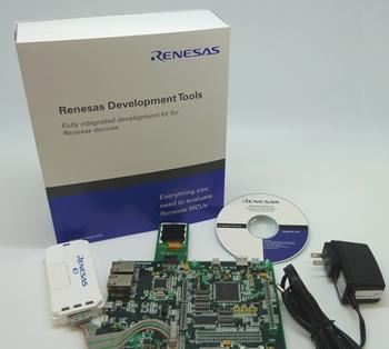
图2. RX64M RX64M入门套件外形图

图3. RX64M RX64M入门套件扩展板外形图
图4. RX64M CPU板和HMI扩展板系统配置图
图5.HMI扩展板系统框图
责任编辑:HanFeng
【免责声明】
1、本文内容、数据、图表等来源于网络引用或其他公开资料,版权归属原作者、原发表出处。若版权所有方对本文的引用持有异议,请联系拍明芯城(marketing@iczoom.com),本方将及时处理。
2、本文的引用仅供读者交流学习使用,不涉及商业目的。
3、本文内容仅代表作者观点,拍明芯城不对内容的准确性、可靠性或完整性提供明示或暗示的保证。读者阅读本文后做出的决定或行为,是基于自主意愿和独立判断做出的,请读者明确相关结果。
4、如需转载本方拥有版权的文章,请联系拍明芯城(marketing@iczoom.com)注明“转载原因”。未经允许私自转载拍明芯城将保留追究其法律责任的权利。
拍明芯城拥有对此声明的最终解释权。
相关资讯
:
基于MC33771主控芯片的新能源锂电池管理系统解决方案

AMIC110 32位Sitara ARM MCU开发方案

基于AMIC110多协议可编程工业通信处理器的32位Sitara ARM MCU开发方案

基于展讯SC9820超低成本LTE芯片平台的儿童智能手表解决方案

基于TI公司的AM437x双照相机参考设计

基于MTK6580芯片的W2智能手表解决方案


 2012- 2022 拍明芯城ICZOOM.com 版权所有 客服热线:400-693-8369 (9:00-18:00)


